Installation GuideXPlug A1 EV Charger
Follow this step-by-step guide to safely install and configure your XPlug A1. All steps must be completed in sequence by a qualified electrician.
Box Contents
6 items
What's in the box

Installation Steps
9 Steps
Isolate Power Supply
Isolate the electrical supply before starting installation, and confirm the installation complies with local regulations (e.g. BS 7671 Section 722).
Preparation
Remove the front cover and place it safely to one side.
Carefully unwrap the charging cable from the rear enclosure, and place the vehicle connector on the floor to avoid dropping it during installation.
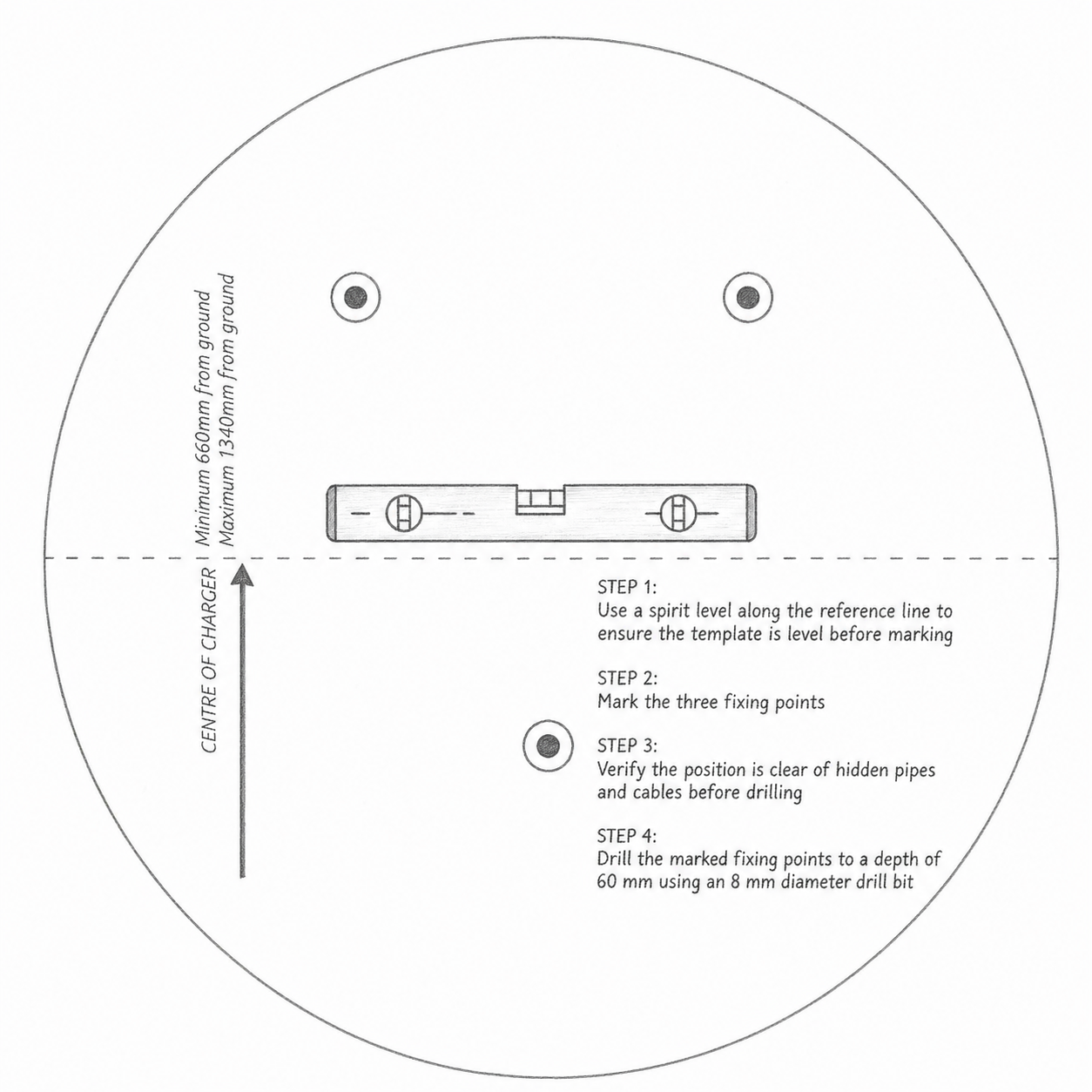
Positioning
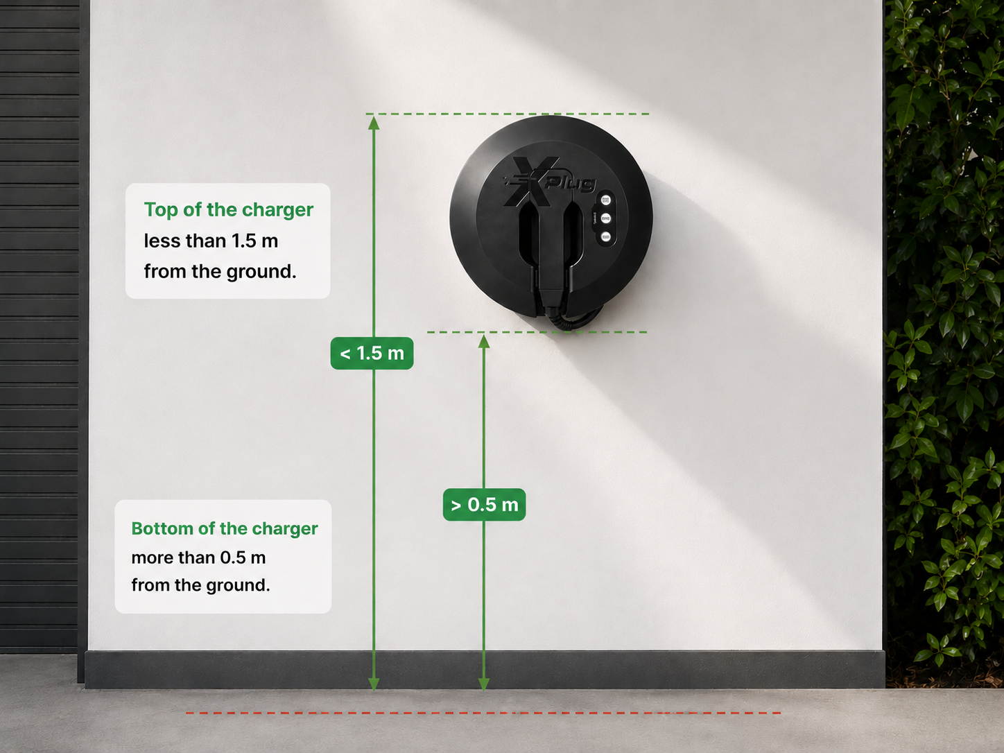
Select a suitable installation location. The charger must be mounted so that the bottom of the charger is more than 0.5 m from the ground, and the top of the charger is less than 1.5 m from the ground.

Marking
Place the mounting template at the intended location.
Mark all fixing hole positions clearly on the wall surface.
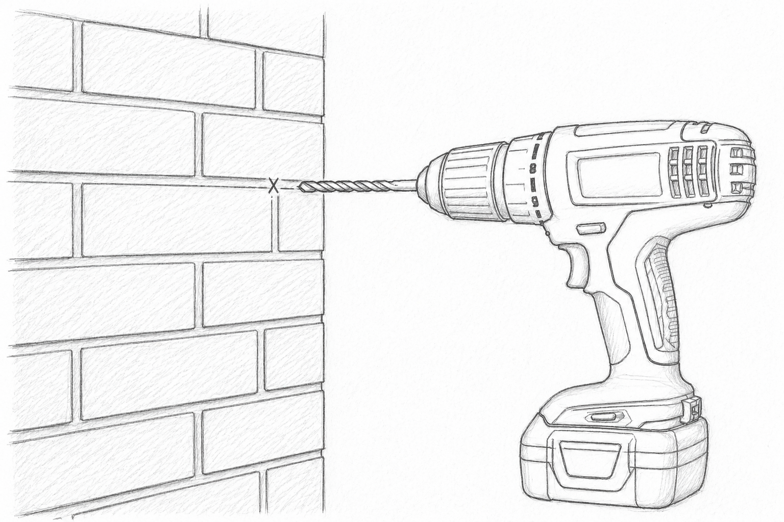
Drilling
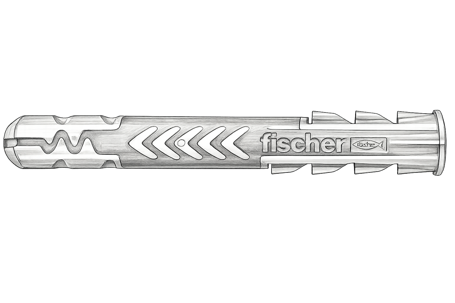
Using an 8 mm diameter drill bit, drill fixing holes at the marked positions to a depth of 60 mm.
Ensure the holes are clean and free from dust before inserting the supplied wall plugs fully into each hole.
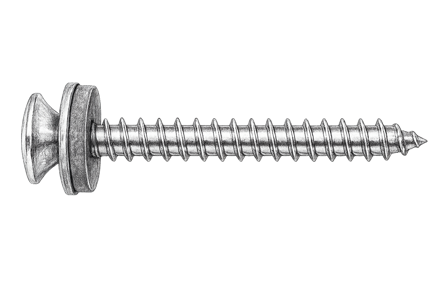
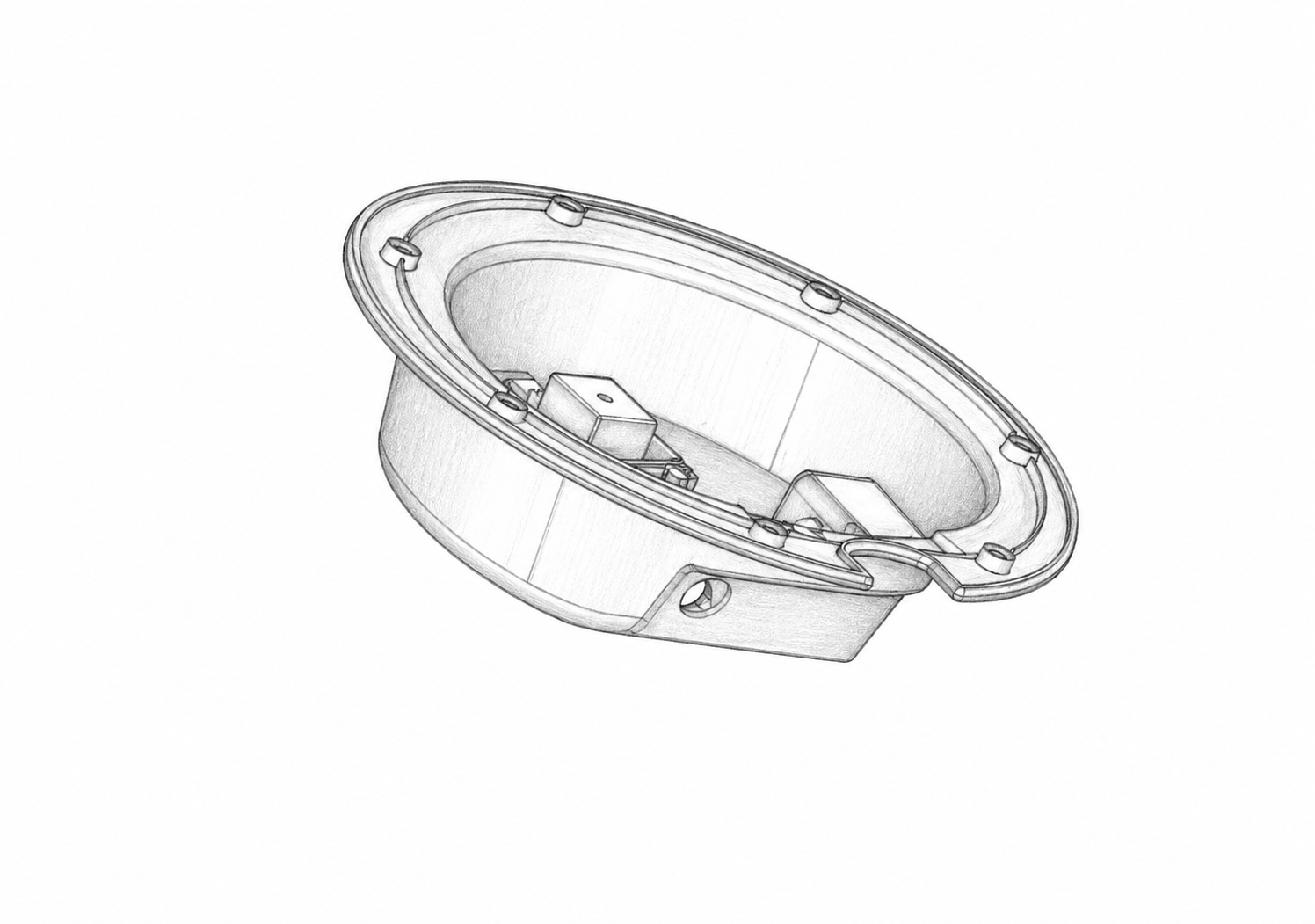
Wall Mounting
Secure the rear enclosure to the wall using the supplied fixing screws.
Tighten all screws evenly to ensure the enclosure is firmly mounted and flush with the wall surface.
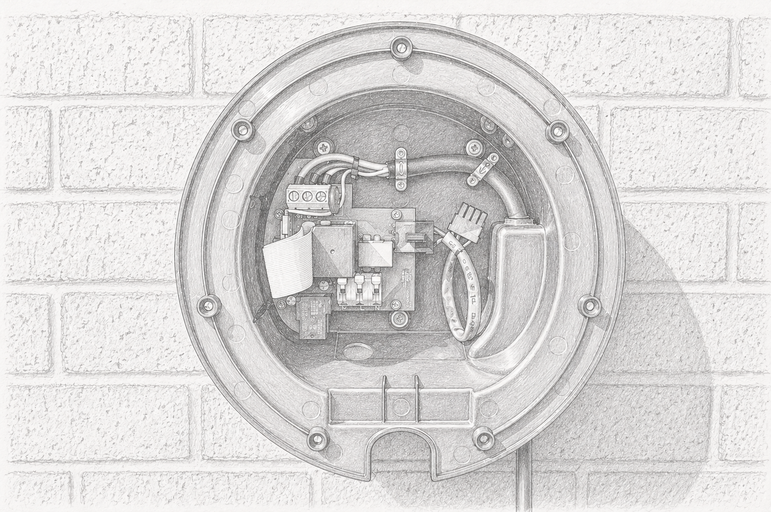
Cable Gland Installation
Bring the supply cable into the unit and secure it with a suitable gland, ensuring it is fully tightened to maintain the IP rating.
Use a Type A RCD (≤30 mA, 40 A recommended); no earth rod is typically required for TN-C-S installations.
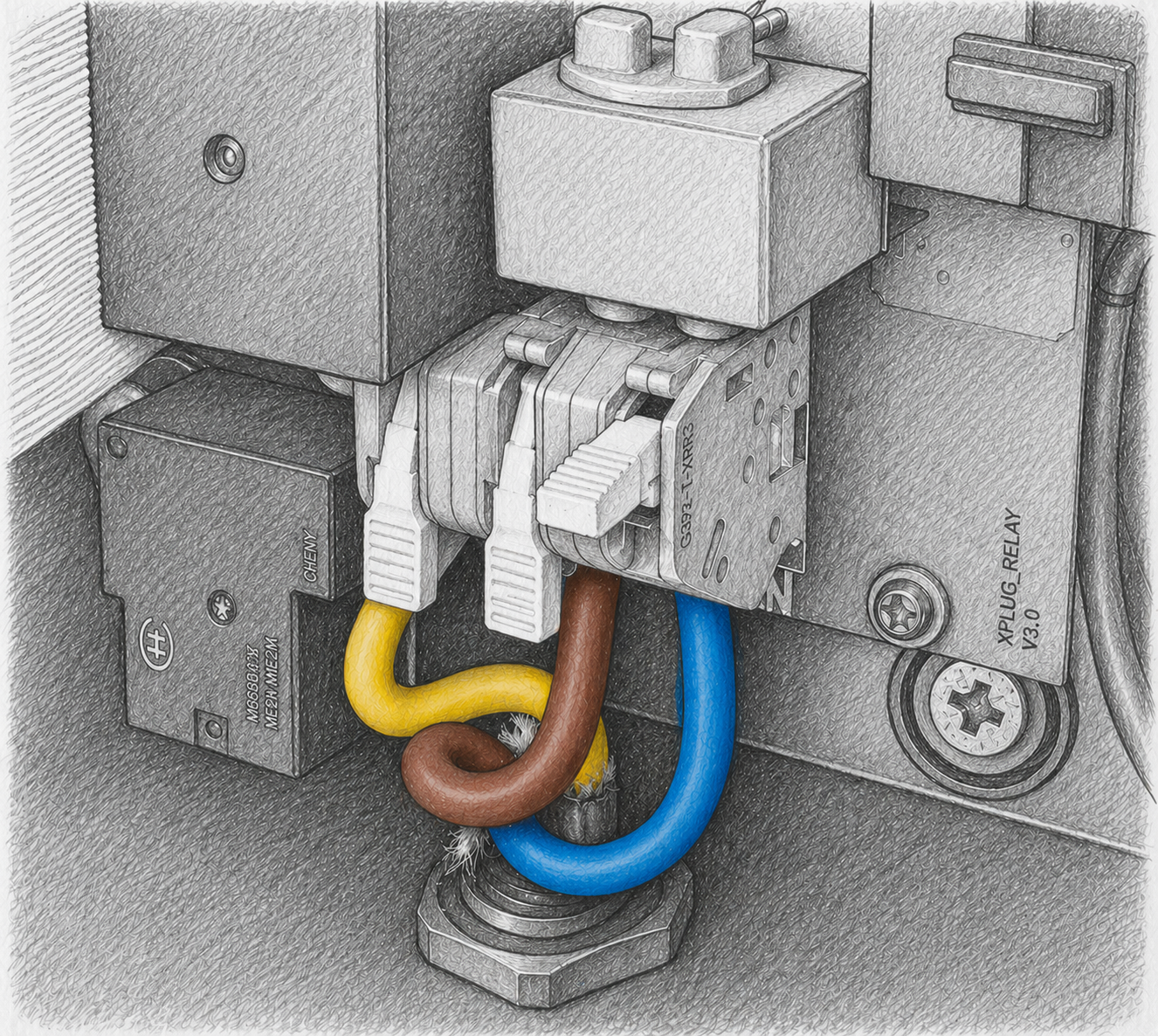
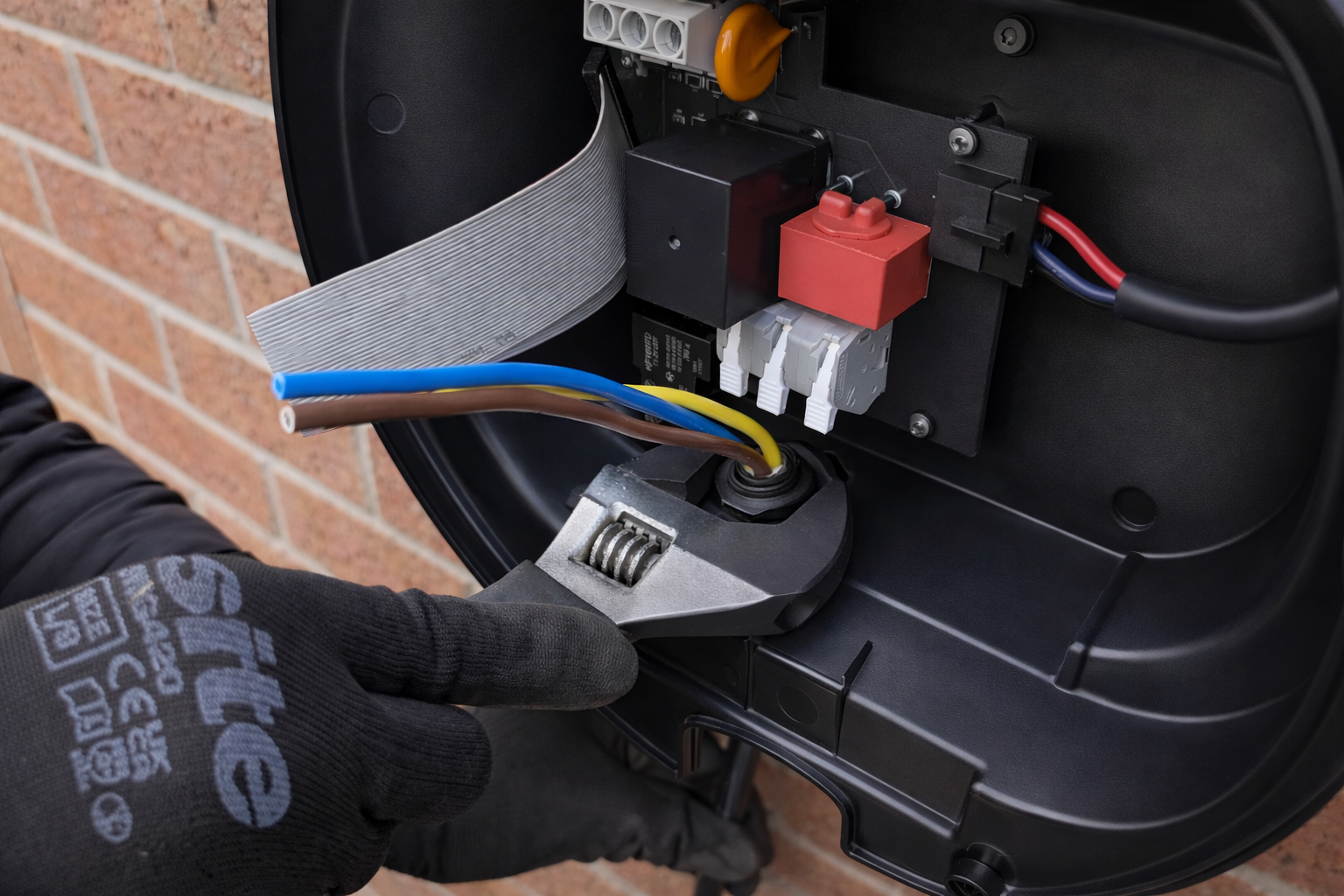
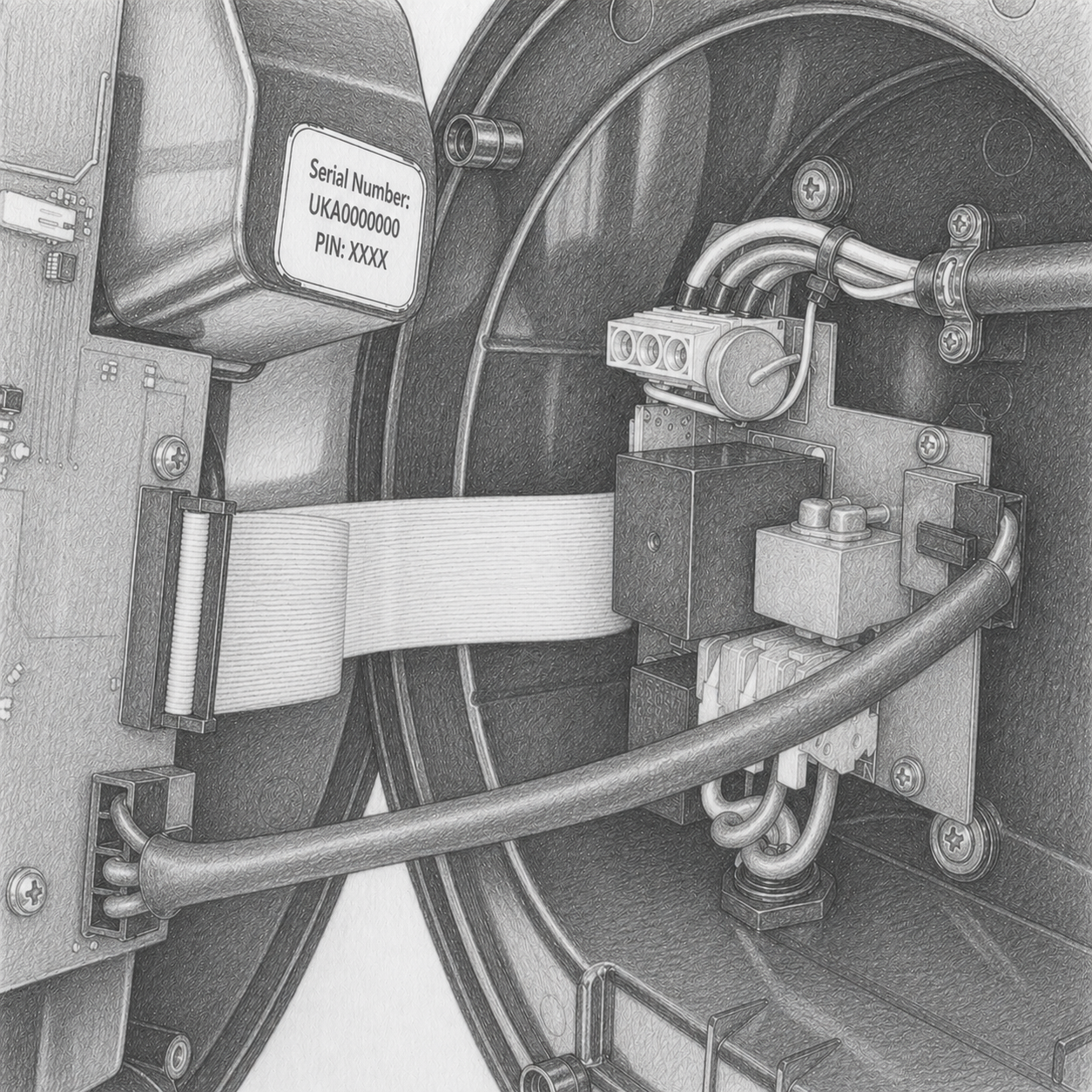
Electrical Connection
With the supply isolated, strip 15 mm of insulation and connect the Earth (left), Live (centre), and Neutral (right) conductors into the terminal block.
Ensure all conductors are fully inserted and seated correctly.
Final Assembly
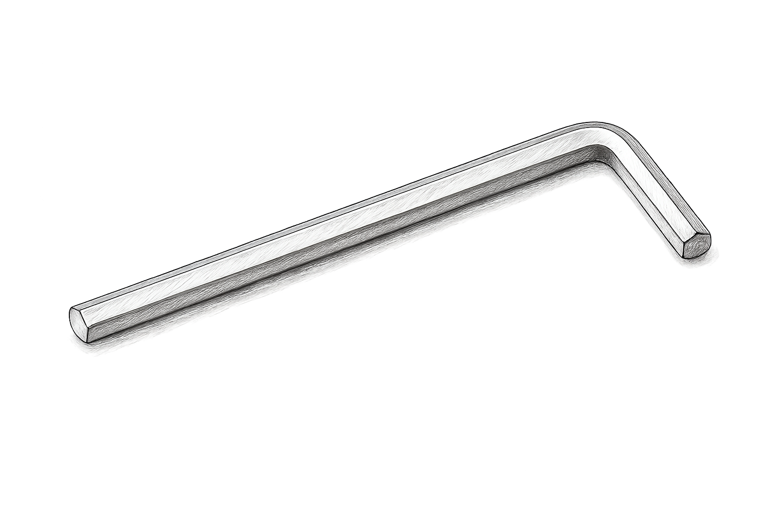
Connect internal wiring harnesses. Position the front cover and secure it using the 7 supplied bolts with the provided hex key.
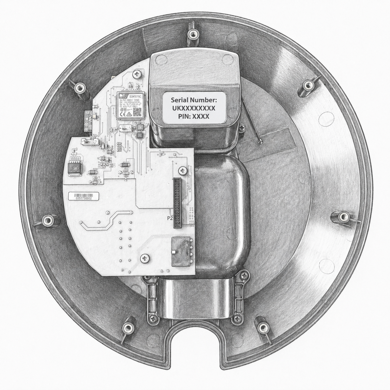
Record the Serial Number and PIN before completing the installation.
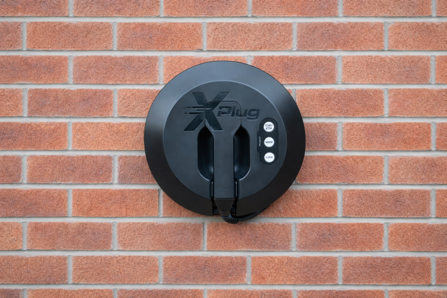
Your XPlug A1 is ready to charge
Congratulations — installation is complete. Download the XPlug App to manage your charging sessions, set schedules and view usage statistics.